Difference between revisions of "IR Shield/en"
m |
m |
||
| (5 intermediate revisions by the same user not shown) | |||
| Line 22: | Line 22: | ||
|} | |} | ||
| − | == | + | ==电气特性== |
{| class="wikitable" | {| class="wikitable" | ||
|- | |- | ||
| − | | align="center" style="background:#f0f0f0;"|''' | + | | align="center" style="background:#f0f0f0;"|'''参数''' |
| − | | align="center" style="background:#f0f0f0;"|''' | + | | align="center" style="background:#f0f0f0;"|'''最小值''' |
| − | | align="center" style="background:#f0f0f0;"|''' | + | | align="center" style="background:#f0f0f0;"|'''经典值''' |
| − | | align="center" style="background:#f0f0f0;"|''' | + | | align="center" style="background:#f0f0f0;"|'''最大值''' |
| − | | align="center" style="background:#f0f0f0;"|''' | + | | align="center" style="background:#f0f0f0;"|'''单位''' |
|- | |- | ||
| − | | | + | | 电源||4.5||5||5.5||VDC |
|- | |- | ||
| − | | | + | | 最高输入电压 (Target Voltage = 3.3V)||3||3.3||3.6||V |
|- | |- | ||
| − | | | + | | 最高输入电压 VinH (Target Voltage = 5V)||4.5||5||5.5||V |
|- | |- | ||
| − | | | + | | 最低输入电压||-0.3||0||0.5||V |
|- | |- | ||
| − | | | + | | 电流||-||40||-||mA |
|} | |} | ||
| − | == | + | ==硬件图== |
[[File:IM140715001pic1.jpg|500px]] | [[File:IM140715001pic1.jpg|500px]] | ||
[[File:IM140715001pic2.jpg|500px]] | [[File:IM140715001pic2.jpg|500px]] | ||
[[File:IM140715001pic3.jpg|500px]] | [[File:IM140715001pic3.jpg|500px]] | ||
| − | == | + | ==引脚图== |
{| class="wikitable" | {| class="wikitable" | ||
|- | |- | ||
| − | | align="center" style="background:#f0f0f0;"|''' | + | | align="center" style="background:#f0f0f0;"|'''Arduino引脚''' |
| − | | align="center" style="background:#f0f0f0;"|''' | + | | align="center" style="background:#f0f0f0;"|'''描述''' |
|- | |- | ||
| D0||XBEE_TX | | D0||XBEE_TX | ||
| Line 94: | Line 94: | ||
|- | |- | ||
|} | |} | ||
| − | *IR_TX: | + | *IR_TX: 当D3设置为高电平,红外发射管会向外发射信号;当D3设置为低电平,红外发射管不工作。 |
| − | + | ||
| − | + | ||
| − | + | ||
| − | + | ||
| − | + | ||
| − | + | ||
| − | + | ||
| − | == | + | *IR_RX: 使用HS0038B作为IR接收模块。 |
| − | + | ||
| + | *Jumpers:跳线帽是直接连接到Arduino的IO 上,如果不需要或引脚被其他模块占用时,请移除其跳线帽。 | ||
| + | |||
| + | :A0:上拉一个10K电阻到A0按钮上。 | ||
| + | |||
| + | :LED1:连接到D6引脚,置高时LED1会亮。 | ||
| + | |||
| + | :LED2:连接到D7引脚,置高时LED2会亮。 | ||
| + | |||
| + | *Switch:根据Arduino主板的操作电平来设置,当主板工作在5V,开关打到5V;当主板工作在3.3V,开关打到3V3。 | ||
| + | |||
| + | ==使用指南== | ||
| + | 请参看博文: | ||
http://blog.iteadstudio.com/diy-intelligent-monitor-for-home-temperature-and-humidity/ | http://blog.iteadstudio.com/diy-intelligent-monitor-for-home-temperature-and-humidity/ | ||
| − | == | + | ==文件下载== |
| − | * | + | *原理图--[[:File:IM140715001-IR Shield-schematic.pdf]] |
| − | *IR Receiver | + | *IR Receiver 数据--[[:File:IM140715001-HS0038B.pdf]] |
| − | *SHT1x | + | *SHT1x 数据--[[:File:SHT1x_Datasheet.pdf]] |
*Temperature & Humidity sensor demo--[[:File:Sht10.zip]] | *Temperature & Humidity sensor demo--[[:File:Sht10.zip]] | ||
| − | == | + | ==相关链接== |
http://blog.iteadstudio.com/diy-intelligent-monitor-for-home-temperature-and-humidity/ | http://blog.iteadstudio.com/diy-intelligent-monitor-for-home-temperature-and-humidity/ | ||
Latest revision as of 02:07, 9 August 2014
Overview
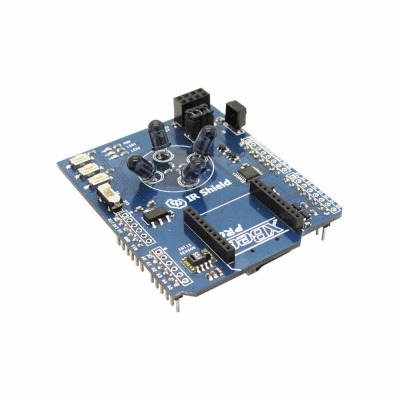
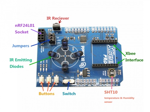
IR Shield is designed for Arduino, which is equipped with infrared receiving and dispatching module, nRF24L01 interface, Xbee interface, Micro SD slot and temperature and humidity sensor. With this IR shield, you can intelligentize your home by making a DIY monitor for indoor temperature and humidity or a controller for IR home appliances such as air-condition and television.
Go shopping
特点
- 兼容5/3.3V主板
- micro SD卡接口
- XBee 接口
规格
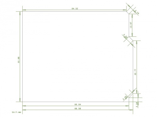
| PCB尺寸 | 55.88mm X 68.58mm X 1.6mm |
| 电压 | 5V DC |
| 指示灯 | PWR,LED1,LED2 |
| 接口 | UART,IIC,SPI |
电气特性
| 参数 | 最小值 | 经典值 | 最大值 | 单位 |
| 电源 | 4.5 | 5 | 5.5 | VDC |
| 最高输入电压 (Target Voltage = 3.3V) | 3 | 3.3 | 3.6 | V |
| 最高输入电压 VinH (Target Voltage = 5V) | 4.5 | 5 | 5.5 | V |
| 最低输入电压 | -0.3 | 0 | 0.5 | V |
| 电流 | - | 40 | - | mA |
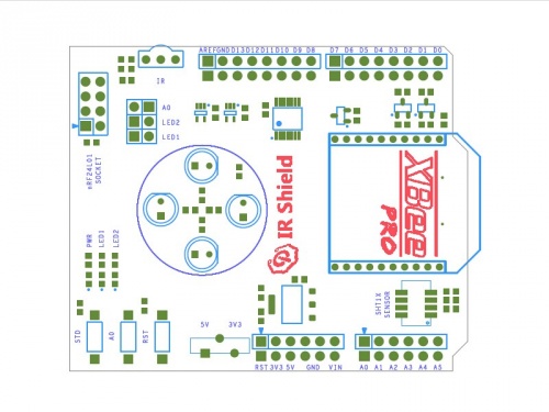
硬件图
引脚图
| Arduino引脚 | 描述 |
| D0 | XBEE_TX |
| D1 | XBEE_RX |
| D2 | nRF24L01_IRQ & STD Button |
| D3 | IR_TX* |
| D4 | SD_CS |
| D5 | IR_RX* |
| D6 | LED1* |
| D7 | LED2* |
| D8 | - |
| D9 | nRF24L01_CE |
| D10 | nRF24L01_CS |
| D11 | MOSI |
| D12 | MISO |
| D13 | SCK |
| A0 | A0 Button |
| A1 | - |
| A2 | - |
| A3 | - |
| A4 | SHT10_SDA |
| A5 | SHT10_SCL |
- IR_TX: 当D3设置为高电平,红外发射管会向外发射信号;当D3设置为低电平,红外发射管不工作。
- IR_RX: 使用HS0038B作为IR接收模块。
- Jumpers:跳线帽是直接连接到Arduino的IO 上,如果不需要或引脚被其他模块占用时,请移除其跳线帽。
- A0:上拉一个10K电阻到A0按钮上。
- LED1:连接到D6引脚,置高时LED1会亮。
- LED2:连接到D7引脚,置高时LED2会亮。
- Switch:根据Arduino主板的操作电平来设置,当主板工作在5V,开关打到5V;当主板工作在3.3V,开关打到3V3。
使用指南
请参看博文:
http://blog.iteadstudio.com/diy-intelligent-monitor-for-home-temperature-and-humidity/
文件下载
- 原理图--File:IM140715001-IR Shield-schematic.pdf
- IR Receiver 数据--File:IM140715001-HS0038B.pdf
- SHT1x 数据--File:SHT1x_Datasheet.pdf
- Temperature & Humidity sensor demo--File:Sht10.zip
相关链接
http://blog.iteadstudio.com/diy-intelligent-monitor-for-home-temperature-and-humidity/
 Notice


