Difference between revisions of "Low-cost Digital Compass Module"
(→Serial Communication Protocol) |
(→Overview) |
||
| (2 intermediate revisions by the same user not shown) | |||
| Line 3: | Line 3: | ||
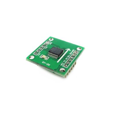
[[File:LOW-COST DIGITAL COMPASS MODULE.jpg|thumb|400px|right]] | [[File:LOW-COST DIGITAL COMPASS MODULE.jpg|thumb|400px|right]] | ||
This is a low cost digital compass with UART and IIC interface, it's easy to use with external controler like Arduino,IFLAT32. | This is a low cost digital compass with UART and IIC interface, it's easy to use with external controler like Arduino,IFLAT32. | ||
| + | |||
| + | Go shopping [http://imall.iteadstudio.com/im120712009.html Low-cost Digital Compass Module (IM120712009)] | ||
==Features== | ==Features== | ||
| Line 57: | Line 59: | ||
Byte7: 0x00 ~ 0xFF checksum (only lower 8bit) | Byte7: 0x00 ~ 0xFF checksum (only lower 8bit) | ||
| − | You can use the Foca or USBtoTLL moudle to connect your PC with this moudle. | + | You can use the [[Foca]] or USBtoTLL moudle to connect your PC with this moudle. |
==IIC Communication Protocol:== | ==IIC Communication Protocol:== | ||
| + | The IIC communication, the module is equivalent to 24C04, EEPROM memory. And you | ||
| + | can read the different address to get the information you need. | ||
| + | |||
| + | {| class="wikitable" | ||
| + | |- | ||
| + | | align="center" style="background:#f0f0f0;"|'''Address''' | ||
| + | | align="center" style="background:#f0f0f0;"|'''Data''' | ||
| + | |- | ||
| + | | 0x00||- | ||
| + | |- | ||
| + | | 0x01||Angle value high 8bit | ||
| + | |- | ||
| + | | 0x02||Angle value low 8bit | ||
| + | |- | ||
| + | | 0x03||Magnetic declination high 8bit | ||
| + | |- | ||
| + | | 0x04||Magnetic declination low 8bit | ||
| + | |- | ||
| + | | 0x05||- | ||
| + | |- | ||
| + | | 0x06||- | ||
| + | |- | ||
| + | | 0x07||Calibration Level | ||
| + | |} | ||
| + | |||
| + | ===IIC command:=== | ||
| + | {| class="wikitable" | ||
| + | |- | ||
| + | | align="center" style="background:#f0f0f0;"|'''Command''' | ||
| + | | align="center" style="background:#f0f0f0;"|'''Description''' | ||
| + | |- | ||
| + | | 0x00+0x31||Angle measurement | ||
| + | |- | ||
| + | | 0x00+0xC0||Start calibration | ||
| + | |- | ||
| + | | 0x00+0xC1||Stop calibration | ||
| + | |- | ||
| + | | 0x00+0xA0+0XAA+0XA5+0XC5||Restore default setting | ||
| + | |- | ||
| + | | 0x00+(0xA0+0XAA+0XA5+IIC_ADDR)||Change IIC address of the module | ||
| + | |- | ||
| + | | 0x03+ 8bit||Magnetic declination changes (high 8bit) | ||
| + | |- | ||
| + | | 0x04+ 8bit||Magnetic declination changes (low 8bit) | ||
| + | |} | ||
| + | |||
| + | *Default IIC address is 0xE0. | ||
==Download== | ==Download== | ||
| + | [ftp://imall.iteadstudio.com/Modules/IM120712009/DS_IM120712009.pdf Datasheet] | ||
==Useful Links== | ==Useful Links== | ||
Latest revision as of 08:11, 11 June 2014
Contents
Overview
This is a low cost digital compass with UART and IIC interface, it's easy to use with external controler like Arduino,IFLAT32.
Go shopping Low-cost Digital Compass Module (IM120712009)
Features
- Small size
- Uart or IIC doulbe output/control interface
- 3-5V Voltage comaptible
Specifications
| Measuring range | 0-360 ° |
| Resolution | 0.1 |
| Accuracy | 1° |
| Power supply | 3V-5V DC |
| Frequency response | 25Hz |
| Current | 5 V--15mA 3V--8 mA |
| Size | 25.6mm×25.6mm |
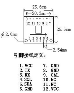
Hardware
Serial Communication Protocol
Baud rate:
9600 bps Parity: N data bits: 8 Stop bit: 1
Command
0x31: the first angle measurement 0xC0: calibration of the magnetic field start 0xC1: the end of the calibration magnetic field 0xA0-0XAA-0XA5-0XC5: Restore default setting 0xA0-0XAA-0XA5-IIC_ADDR: IIC address of the module change 0x03 + 8bit: Setting the magnetic declination high 8 bit 0x04 + 8bit: Setting the magnetic declination low8 bit
Return Data
Byte0: 0x0D Byte1: 0x0A Byte2: 0x30 ~ 0x33 angle of one hundred (ASCII 0 ~ 3) Byte3: 0x30 ~ 0x39 angle of ten (ASCII 0 ~ 9) Byte4: 0x30 ~ 0x39 angle a bit (ASCII 0 ~ 9) Byte5: 0x2E (ASCII code decimal point) Byte6: 0x30 ~ 0x39 decimal point (ASCII 0 ~ 9) Byte7: 0x00 ~ 0xFF checksum (only lower 8bit)
You can use the Foca or USBtoTLL moudle to connect your PC with this moudle.
IIC Communication Protocol:
The IIC communication, the module is equivalent to 24C04, EEPROM memory. And you can read the different address to get the information you need.
| Address | Data |
| 0x00 | - |
| 0x01 | Angle value high 8bit |
| 0x02 | Angle value low 8bit |
| 0x03 | Magnetic declination high 8bit |
| 0x04 | Magnetic declination low 8bit |
| 0x05 | - |
| 0x06 | - |
| 0x07 | Calibration Level |
IIC command:
| Command | Description |
| 0x00+0x31 | Angle measurement |
| 0x00+0xC0 | Start calibration |
| 0x00+0xC1 | Stop calibration |
| 0x00+0xA0+0XAA+0XA5+0XC5 | Restore default setting |
| 0x00+(0xA0+0XAA+0XA5+IIC_ADDR) | Change IIC address of the module |
| 0x03+ 8bit | Magnetic declination changes (high 8bit) |
| 0x04+ 8bit | Magnetic declination changes (low 8bit) |
- Default IIC address is 0xE0.
 Notice
