Difference between revisions of "SIM900/SIM900A GSM/GPRS Minimum System Module"
From ITEAD Wiki
(→Electrical Characteristics) |
(→Hardware) |
||
| Line 52: | Line 52: | ||
==Hardware== | ==Hardware== | ||
| + | [[File:GPRS module1.jpg]] | ||
| + | |||
| + | {| class="wikitable" | ||
| + | |- | ||
| + | | align="center" style="background:#f0f0f0;"|'''Interface''' | ||
| + | | align="center" style="background:#f0f0f0;"|'''Pin''' | ||
| + | | align="center" style="background:#f0f0f0;"|'''Description''' | ||
| + | |- | ||
| + | | Rst||1||Reset the SIM900 module | ||
| + | |- | ||
| + | | P||2||Power switch pin of SIM900 module | ||
| + | |- | ||
| + | | Tx||3||UART data output | ||
| + | |- | ||
| + | | Rx||4||UART data in | ||
| + | |- | ||
| + | | DT||5||Debug UART data output | ||
| + | |- | ||
| + | | DR||6||Debug UART data input | ||
| + | |- | ||
| + | | -||7||GND | ||
| + | |- | ||
| + | | +||8||VCC | ||
| + | |} | ||
==Installation== | ==Installation== | ||
Revision as of 03:48, 29 May 2014
Contents
Overview
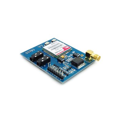
GPRS module is a breakout board and minimum system of SIM900 Quad-band/SIM900A Dual-band GSM/GPRS module. It can communicate with controllers via AT commands (GSM 07.07 ,07.05 and SIMCOM enhanced AT Commands). This module supports software power on and reset.
Features
- Quad-Band 850/ 900/ 1800/ 1900 MHz
- Dual-Band 900/ 1900 MHz
- GPRS multi-slot class 10/8GPRS mobile station class B
- Compliant to GSM phase 2/2+Class 4 (2 W @850/ 900 MHz)
- Class 1 (1 W @ 1800/1900MHz)
- Control via AT commands (GSM 07.07 ,07.05 and SIMCOM enhanced AT Commands)
- Low power consumption: 1.5mA(sleep mode)
- Operation temperature: -40°C to +85 °C

Specifications
| PCB size | 71.4mm X 66.0mm X1.6mm |
| Indicators | PWR, status LED, net LED |
| Power supply | 5V |
| Communication Protocol | UART |
| RoHS | Yes |
Electrical Characteristics
| Parameter | Min. | Typical | Max. | Unit |
| Power voltage (Vsupply) | 4.5 | 5.5 | VDC | |
| Input voltage VH | 0.7VCC | 5.5 | V | |
| Input voltage VL | -0.3 | 0 | 0.3VCC | V |
| Current Consumption (pulse) | - | 2000 | mA | |
| Current Consumption (continuous) | 500 | mA | ||
| Baud rate | 115200 | bps |
Hardware
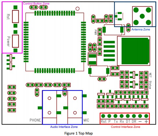
| Interface | Pin | Description |
| Rst | 1 | Reset the SIM900 module |
| P | 2 | Power switch pin of SIM900 module |
| Tx | 3 | UART data output |
| Rx | 4 | UART data in |
| DT | 5 | Debug UART data output |
| DR | 6 | Debug UART data input |
| - | 7 | GND |
| + | 8 | VCC |
Installation
Power on GPRS module
Indicator LED and Buttons:
Note
In some countries where dual band exists, we recommend to use SIM900A to reduce costs. For the country list, please click here.
 Notice
