Difference between revisions of "HC06 Serial Bluetooth Brick"
(→Electrical Characteristics) |
(→Switch and Indicator) |
||
| Line 50: | Line 50: | ||
==Switch and Indicator== | ==Switch and Indicator== | ||
| + | 1. Resetting button | ||
| + | |||
| + | After pressing down resetting button, module will re-enter standby mode and the status lamp will flash. | ||
| + | |||
| + | 2. Status lamp | ||
| + | |||
| + | When the module is under standby mode, status lamp will keep flashing; when the module is under connection mode, status lamp will keep being ON. | ||
==AT Command== | ==AT Command== | ||
Revision as of 08:09, 27 May 2014
Contents
Overview
What is an electronic brick? An electronic brick is an electronic module which can be assembled like Lego bricks simply by plugging in and pulling out. Compared to traditional universal boards and circuit modules assembled with various electronic components, electronic brick has standardized interfaces, plug and play, simplifying construction of prototype circuit on one’s own. There are many types of electronic bricks, and we provide more than twenty types with different functions including buttons, sensors, Bluetooth modules, etc, whose functions cover from sensor to motor drive, from Ethernet to wireless communication via Bluetooth, and so on. We will continue to add more types to meet the various needs of different projects.
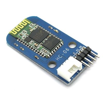
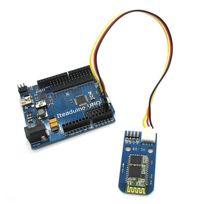
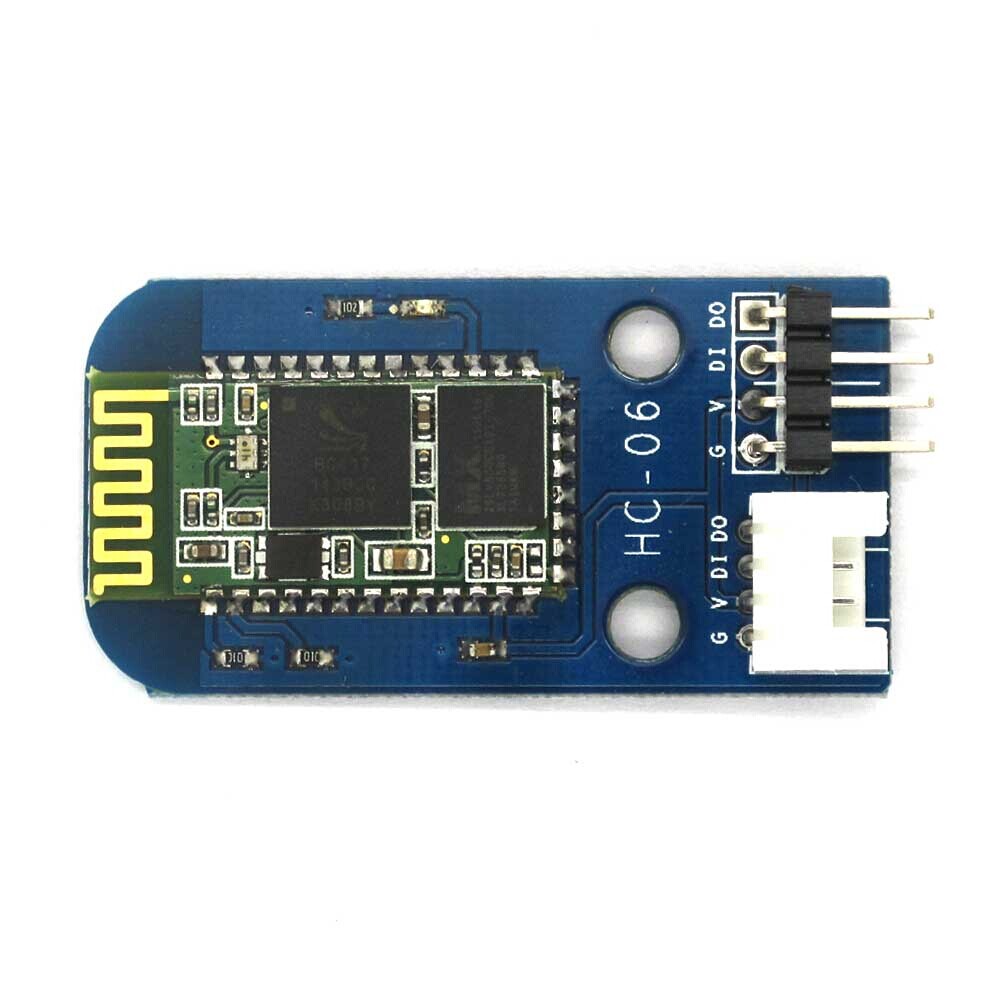
Electronic brick of HC-06 serial port Bluetooth can be connected to hardware UART or analog UART on the control board. With Bluetooth communication, it can achieve wireless transmission which can be applied in various kinds of remote communication occasions.
Features
1. Plug and play, easy to use. Compatible with the mainstream 2.54 buckled interfaces in the market.
2. With resetting button and status indicator
Specifications
| PCB Size | 39.5mm X 20.5mm X 1.6mm |
| Working voltage | 3.3V DC |
| Operating voltage | 3.3V DC |
| Compatible interfaces | 2.544-pin buckled interface(1) |
| Communication protocols | Bluetooth 2.0 |
| Communication range | <20m |
Note 1: DO for data output (TX) port of UART, DI for data input (RX) port of UART, V and G for voltage at the common collector and ground respectively.
Electrical Characteristics
| Parameter | Min. | Typical | Max. | Unit |
| Working voltage | 3 | 3.3 | 4.2 | VDC |
| Digital output voltage(VCC=3.3V) | 0 | - | 3.3 | V |
| Working current(VCC=3.3V) | - | 20 | 40 | mA |
Switch and Indicator
1. Resetting button
After pressing down resetting button, module will re-enter standby mode and the status lamp will flash.
2. Status lamp
When the module is under standby mode, status lamp will keep flashing; when the module is under connection mode, status lamp will keep being ON.
 Notice

